PCIe Long distance Cross node Transmission Solution
.
Quick facts
• Scenario for Scaling AI Clusters Horizontally across Nodes Based on PCIe (Fig-2)
• Long-Distance PCIe Cable Design Prototyping, Signal Processing Methods, Cable Selection (Fig-7/8/10)
.
.

Fig-1
AI infrastructure scaling challenges
1.AI models continue to expand:
• The model size doubled over a 6-month cycle.
• As multimodal data increases, the size of the model will accelerate at an accelerated pace.
2.Requires a larger GPU cluster:
• Fabric networks at scale connect hundreds or thousands of GPUs.
3.Power limited per rack:
• The power consumption of an AI server is 8 times that of a CPU server.
4.Power Limitations:
• GPU cooling is shifting from air cooling to liquid cooling.
Summary: The main challenges facing AI infrastructure include exponential growth in model size, increased demand for GPU clusters, power constraints, and thermal management. This puts tremendous pressure on scaling compute clusters across multiple racks.
.
Fig-2
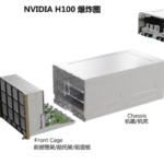
The figure on the left shows the single-rack interconnection communication based on PCIe cables in the current data center, and the cable length is not more than 3m. The next-generation PCIe is expected to be extended to 7m, which has met the interconnection communication of larger clusters.
.
Fig-3
Scale your AI infrastructure based on PCIe
The left rack design has the following highlights:
• A single rack contains general – purpose computing nodes (Compute) and AI acceleration nodes (AI Cluster).
• The design of the acceleration node is not the coupling design of CPU+GPU in the current industry, but draws on the centralized storage architecture to decouple the control node and the computing node to build the AI headnode and the AI accelerated computing array (JBOG) Just Bunch of GPUs, which are interconnected using high-speed PCIe links.
Note
The advantage of this design is that it simplifies the design of the GPU server motherboard, optimizes the space structure and reduces the energy consumption per unit density. However, more dense PCIe lines are required to interconnect nodes.
.
Fig-4
Memory bottlenecks due to AI/ML workloads
AI model complexity doubles every 6 months:
The chart shows that the demand for AI workloads continues to increase (in Petaflops-days).
Higher CPU efficiency and memory expansion capabilities are required.
The memory bandwidth per core is decreasing:
The graph shows the increase in the number of CPU cores, but the memory bandwidth per core is decreasing.
Cause: Memory bandwidth is not keeping up with the speed of CPU expansion.
Server CPU Encapsulation and Thermal Limit Number of Memory Channels:
Due to the package design and thermal management of the CPU, the memory channels are limited.
Result: CPU causes memory bottlenecks, affecting overall performance.
Memory capacity is tied to compute nodes:
In the current design, memory capacity is tightly coupled to compute nodes such as CPUs.
Memory resources are left idle due to the coupled design, resulting in over provisioning.
Note
The objective causes of memory bottlenecks (memory walls) in modern data application systems: the increasing demand for memory capacity (capacity and bandwidth) of AI models, the decrease in memory bandwidth per core due to the multi-core design of servers (inference may still be performed on the CPU), the limited footprints of CPU packaging, and the coupling design of computing and memory nodes.
.
Fig-5
The rise of heterogeneous infrastructure
Converged Infrastructure(Traditional Converged Architecture)
• Peculiarity:
· Each node contains fixed CPUs, memory (DIMMs), storage devices (Drives), GPUs, and network interface cards (NICs).
· The configuration is static and resources are stranded。
· Rigid System Design, Fixed Hosting Costs。
• Issue:
· Resources cannot be dynamically allocated, which is easy to cause waste.
· Lack of flexibility to adapt to different workload needs.
Operation and maintenance cost challenges(OPEX Challenges)
• High PUE (Power Inefficiency): Traditional architectures have high heat dissipation and power management costs.
• Thermal management challenges: Dense hardware distribution makes it difficult to effectively dissipate heat concentration.
• Complex software performance optimization: Traditional architectures require complex performance tuning due to resource coupling.
—
Disaggregated/Composable Infrastructure(Decoupled/Composable Architecture)
• Features:
· Various hardware resource modules (such as CPUs, NICs, storage devices, memory, and GPUs) exist independently and are dynamically interconnected through PCIe/CXL switches.
· Different types of hardware resources can be flexibly combined according to workload requirements.
• Advantages:
· Efficient Performance:Hardware resources are combined as needed to maximize resource utilization.
· Flexible Cost Model:Resources are no longer fixed, reducing hosting and expansion costs.。
· Low PUE (Power Usage Effectiveness): Centralized cooling design for more efficient thermal management.
· Bare-Metal Performance:Reduce the performance losses of virtualization and resource isolation。
Decoupled and composable architectures can dynamically combine hardware based on workload requirements by modularizing hardware resources and leveraging high-speed interconnects (such as PCIe/CXL), significantly improving resource efficiency, reducing costs, and simplifying O&M. This architecture is particularly well-suited to the needs of diverse AI/ML workloads and dynamic cloud computing environments. Compared to traditional converged architectures, it has higher flexibility and performance optimization potential.
Fig-6
PCIe-based Memory Scaling CPU Compute Nodes (JBOM)
Fig-7
PCIe cabling schemes
External Cabling Reach Considerations
1. Within-the-rack
• Scenario: For example, the headnode of an AI server is connected to a GPU array (JBOG).
• Tehchnology:Use PCIe passive DAC(Direct Attach Cable)和Aries Active Riser Card。
• Coverage: cable length up to 3 meters.
• Characteristic:
· Support Full PCIe channel budget。
2. Across-racks
• Scenario: For example, the connection between JBOGs.
• Technology: Use PCIe AEC (Active Electrical Cable, requiring a Retimer to strengthen the signal) with integrated signal shaping (Integrated Retimer).
• Coverage: cable length up to 7 meters.
• Characteristic:
· Provides signal regeneration to ensure data transmission integrity.
· Supports full PCIe channel budgets.
3. Across-rows
• Scenario: A possible switch-to-switch connection in the future.
• Technology:Use PCIe AOC(Active Optical Cable),with integrated signal shaping.
• Coverage: Fiber length up to 50 meters.
• Characteristic:
· Optical fiber is used for ultra-long-distance transmission.
· It is limited by Latency and PCIe Retry Buffer Depth),rather than the optical or electrical technology itself.
1.Short range (in-rack, 3 meters): Uses a passive DAC for tight physical layouts.
2.Mid-range (rack-to-rack, 5-7 meters): AEC is used for signal enhancement to meet multi-rack cabling requirements.
3.Long distances (inter-row, 20-50 meters): AOC, based on fiber optic technology, can support a wider range of equipment connections in the data center.
These designs effectively meet the needs of large-scale AI computing clusters from within the rack to across rows by optimizing signal transmission technologies over different distances.
The role of Retimer in signal transmission over long distances
Retimer is an important component for improving signal integrity and reliability in high-speed signal transmission over long distances. It overcomes quality issues caused by attenuation and interference during signal transmission by retiming and equalizing the signal. The following are its main roles in long-distance signal transmission:
1.Signal Regeneration:
• As a signal travels over long distances in a cable or fiber, its amplitude is diminished and it is affected by noise and interference. Retimer reschedules and redrives the signal to its original high-quality state, avoiding an increase in the data bit error rate (BER).
2.Extended Transmission Distance:
• In high-speed transmission protocols such as PCIe or CXL, the physical distance over which a signal can be transmitted is limited by bandwidth and attenuation. The addition of the Retimer can significantly extend transmission distances, e.g. from 3 meters to 7 meters with conventional cables, or even up to 50 meters with fiber optic cables.
3.Jitter Reduction:
• Signal jitter is a common problem in high-speed transmissions, affecting timing and data integrity. Retimer re-times the data stream to remove signal jitter and ensure reliable transmission.
4.Multi-link extension support:
• In multi-link (e.g., multiple GPUs, JBOG) connections, Retimer guarantees that the signal for each link is independent and complete, enabling complex multi-rack deployments.
.
Fig-8
Comparison of PCIe AECs signal processing techniques
.
.
.
.
.
.
.
.
.
.
.
.
.
PCIe Sideband Signals | Descriptions | Matters to be dealt with in AEC | Alternative solution |
REFCLK | 100MHz HCSL clock, with or without spread spectrum modulation support | Use a dedicated differential pair to transmit REFCLK from one end to the other. Advantages: Supports common clock topologies. Disadvantages: Increases cable cost and the cable design is “asymmetric”. | The cable does not transmit REFCLK: Use SRNS/SRIS. Advantages: Lower cost, the cable is “symmetric”; can be extended to multi – link AEC. Disadvantages: The CC topology requires a dedicated side – band cable between systems. |
PERST# | PCIe protocol reset | Use a dedicated single – ended line to transmit PERST#. Advantages: Supports PERST# synchronization based on each link.
Disadvantages: Increases cable cost and the cable design is “asymmetric”. | The cable does not transmit PERST#. PCIe reset events are handled through in – band thermal reset, host – coordinated local reset, side – band management, or hot – swap support.
Advantages: Lower cost, the cable is “symmetric”; can be extended to multi – link AEC.
Disadvantages: There is no dedicated PERST# for each link. |
PRSNT# | Cable Presence Indicator | Pluggable cable MSAs (such as OSFP, OSFP – XD, etc.) already include the ModPrsL function. | Not applicable. |
The table illustrates the functional descriptions of the three PCIe sideband signals (REFCLK, PERST#, PRSNT#), how they are handled in AEC, and their alternatives. Each solution has advantages and disadvantages, and it is necessary to choose the appropriate treatment method according to the actual needs.
.
Fig-9
AECs:Comparison between PCIe and Ethernet
The main differences between the two:
1.Protocol Complexity:
• The protocol structure is simpler and does not have the complexity of PCIe.
• Backward compatibility is supported.
• Requires complex Link Training.
• Requires complex Link Training.
2.Interoperability:
• It is generally suitable for a unified network equipment environment with relatively few interoperability requirements.
• Supports multiple device types and ecosystem participants (e.g., GPUs, storage, networking devices, etc.).
• Broader interoperability needs.
Detailed comparison:
PCI Express(Include CXL):
• State Diversity:
· Contains multiple Training States for device discovery, linkwidth/speed configuration, protocol negotiation, and more.
· Low-power States:L0、L1、L2、L0s、L0p。
· Recovery States:Used to address performance degradation.
· Special status:Such as Reset、Hot Reset、Disabled。
• Complexity:
· The protocol state diagram is complex, and the link initialization and training process is long.
· It is suitable for scenarios that require high-performance and complex device connectivity, such as AI acceleration and storage expansion.
Ethernet:
• The status is simple:
· Basically, there are only two main states: Link-Down and Link-Up, with a transition training state in between.
• Limitations:
· There is no dedicated state/protocol to perform a link reset or disable.
· Low-power states are not supported.
· Link configuration status is not supported.
• Simplified design:
· The state diagram is simple and the link initialization is fast, which is suitable for general network scenarios.
Brief summary:
• Features of PCIe:
· Complex protocols that support more advanced device discovery, link configuration, and low-power states.
· More suitable for applications that require high bandwidth and complex topologies, such as AI, storage, and compute acceleration.
• Features of Ethernet:
· The protocol is simple, the state is small, and the link establishment speed is fast.
· It is more suitable for network communication scenarios, with low complexity but lack advanced functions.
Therefore, PCIe is more suitable for high-speed interconnection computing and storage scenarios, while Ethernet is more suitable for large-scale, low-complexity network connection applications.
.
Fig-10
PCIe cable selection
The key point of contrast
1.Number and size of channels:
• The OSFP-XD offers up to 16 channels while the PCB size is more compact (2292 mm²).
• QSFP offers a minimum of 4 lanes but has a larger PCB area.
2.Cable Support & Length:
• All form factors support both passive DAC and active AEC.
• At 64 GT/s, the DAC supports a maximum of 3-4 meters and the AEC supports 5-6 meters.
3.Power Capacity:
• OSFP and OSFP-XD have the highest power capability per channel, approx. 4.125W/channel, making them suitable for high-performance applications.
• QSFP has the lowest power per channel, 2.5W/channel, which is more suitable for low-power scenarios.
4.Fiber Optic Cable Support:
• With the exception of CDFP, all other form factors support Active Optical Cables (AOC) for efficient transmission over longer distances.
The table shows the differences in PCIe cabling specifications, allowing you to choose the right cabling solution based on bandwidth requirements, power requirements, and distance.
.
Fig-11
1.SFF-TA-1032 (CDFP) Use two physical Paddle Cards in the cable assembly.
Paddle Card)。
2.This presents an important challenge: how do you connect the Tx and Rx signals from the different paddle cards into the Retimer assembly?
3.The necessity of simultaneous termination of Rx and Tx signals in the Retimer:
• Used for Equalization Phase 2/3 Training.
• Used for In-band Lane Marginaling
Technical details:
• The diagram above shows the pinout of the paddle card, which is divided into the Upper Paddle Card Pinout and the Lower Paddle Card Pinout.
• The role of Retimer is to retime and correct the transmit (Tx) and receive (Rx) signals in different paddle cards to ensure signal quality.
.
Fig-12
Wrap Up
1.Evolved AI and Decoupled Computing System Topologies:
• More External Cabling is required to accommodate complex system architectures.
2.Coverage Requirements:
• 2 meters: suitable for in-rack wiring.
• 7 meters: suitable for cabling between racks.
• More than 7 meters: suitable for larger-scale cluster deployments.
3.AEC & Optical Solutions Supported by Retimer:
• Supports extended signal transmission distances while providing an easy-to-design PCIe-compliant interface for hosts/devices.
• The addition of Retimer ensures the quality and integrity of the signal and is key to transmission over long distances.
4.PCIe AEC and the complexity of optical design
• PCIe’s protocol and interoperability design is more complex than Ethernet.
• Compatibility involving multiple protocol layers, adapting to different types of devices and ecosystems.
5.Application benefits of OSFP-XD/OSFP:
• For PCIe/CXL x16/x8 applications, OSFP-XD/OSFP is an attractive option.
• Supports passive DAC, active AEC, and optical solutions for a wide range of cabling needs.
.
.
.